Pre-installation
How To Install TankBoost
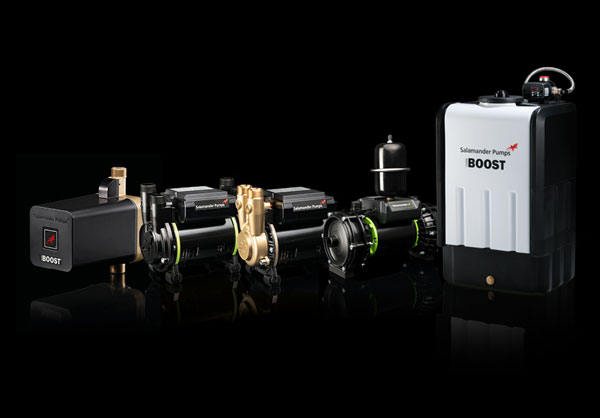
TankBoost is designed for mains-fed systems requiring a higher water supply. It will boost the water to multiple outlets and across multiple floors, all at the same time. TankBoost is a single unit solution for domestic and light commercial situations, delivering up to either 3.0 Bar and 80 L/min or 5.0 Bar and 120 L/min.
You should familiarise yourself with the Installation Guide before beginning the install and refer to it throughout. Alongside this, you can call our technical team on 0191 516 2002 with any queries.
TankBoost Installation: Key Considerations
Before beginning the installation, you should be aware of the following key considerations:
- Installation must comply with the relevant water regulations or local byelaws.
 Solder fluxes must not come into contact with any part of the unit.
- TankBoost is a potable cold-water tank and should be supplied by the incoming mains only.
- Support all pipework to and from the unit with pipe clips.
- Best practice is to fit full-bore isolating valves on the inlet and outlet pipework to the unit for servicing and maintenance purposes.
- Installing a mains bypass with an isolating valve will support servicing and removal of the unit.
- Do not establish the electrical supply or turn power on until the unit has been filled and air has purged from the pump unit, make the outlet pipework connections once the tank is full.
- During normal installation it is not necessary to adjust the control unit.
Step-by-Step Installation Guide
Please see below for a step-by-step guide for a TankBoost installation.
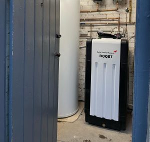
Step 1: Determine Location
Find the location intended for the TankBoost unit, ensuring it is suitable based on the below:
- The floor/mounting surface must be flat, level and able to withstand the maximum full weight of the TankBoost unit.
- We recommend TankBoost is fitted to a suitable supporting wall, to ensure it cannot tip.
- Sufficient space should be left above the unit for maintenance and service access.
- To avoid bacterial growth, you must ensure the stored volume of water remains between 4°C and 20°C. Please ensure that the installation location is protected from extreme temperatures.
- Consider insulation jackets to help to efficiently maintain the water temperature.
- TankBoost is to be installed where light is excluded. Direct sunlight can increase the temperature of the stored water.
- TankBoost must be connected to the electrical supply using the mains cable, wired to a UK 3-pin plug or fused spur (with a 5A fuse for 3.0 Bar units or 10A fuse for 5.0 Bar units). Please ensure that there is an electrical supply close enough to the installation location.
- Surplus electrical cable is provided to enable flexibility on electrical connection to the unit however, excess wiring should be cut to the required length to avoid the cable being coiled.
- If installing where there is a risk of water ingress or condensation to the electrical connection, such as a loft, garage or outbuilding, an appropriately IP rated socket must be used.
Consider foam mats to reduce any noise transfer or vibrations.
Step 2: Unbox TankBoost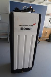
Please note, a 2-person lift may be required to safely locate the TankBoost unit.
- Unbox TankBoost and read enclosed literature.
- Check for any damage to unit.
- TankBoost must be moved into position before installation begins.
Please note: If a drain off point is needed for servicing and maintenance purposes, fit before carrying out the installation.
Step 3: Create The Inlet Connection To TankBoost And A Mains Bypass
- Turn off incoming mains water supply and drain the system.

- Once drained, make a provision for the cold mains to be taken to the unit.
- A draw-off to a drinking water tap should be made before the connection to the TankBoost inlet. This is to ensure a supply of drinking water in the event of an interruption to the power supply.
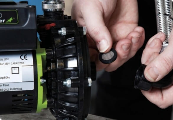
- Ensure that a double check valve has been fitted directly after the mains stop tap to the property. It is also advisable to fit a filter before the inlet to the unit. Salamander Pumps offers an upstream kit, including an inline filter, a double check valve and a pressure reducing valve.
- Fit a full-bore isolating valve to the inlet pipework of TankBoost to facilitate service and removal of the unit.
- Create a mains bypass, fitted with a full-bore isolating valve.
- Open the mains water supply at the stop tap to flush the inlet pipework with water, before connecting to the tank. Close the mains water supply at the stop tap.
- Connect inlet pipework to the TankBoost.
Step 4: Fill TankBoost
- Open all isolating valves supplying TankBoost. The isolating valve on the bypass should remain closed.
- At this point, check for leaks on the inlet pipework.
- Turn mains water on at the stop tap to fully fill the tank with water.
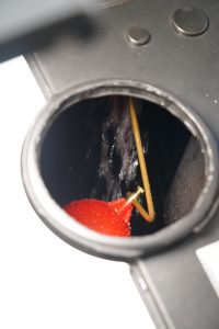
- Check there is at least a 25mm gap between the level of the water when full and where the water exits the inlet valve. Adjust float position if necessary.
Step 5: Make Outlet Connection And Overflow

- Connect outlet pipework to the unit. Salamander Pumps offers outlet connectors for 28mm and 22mm.
- 28mm outlet pipework is recommended from the outlet of the unit to allow maximum flow rate. Smaller diameter pipes may result in reduced flow rates and general product performance.
- Fit a full-bore isolating valve to the outlet pipework of TankBoost to facilitate service and removal of unit.
- 22mm pipework should be fitted to the overflow at the rear of the tank and traced to the nearest drain or outdoor location to prevent flooding in case of failure.
- A tundish can be added to the overflow pipework to allow any overflow to be visible.
Step 6: Open The Outlets
- Open all water outlets and isolation valves (except mains bypass) BEFORE electronically switching the pump on.
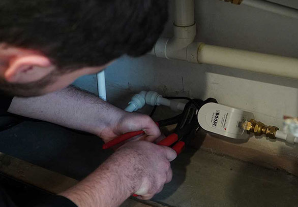
Step 7: Making Electrical Connections
- Connect TankBoost to the electrical supply. TankBoost is supplied with a 3-pin plug or can be connected via a fuse spur (with a fuse no greater than 5A for 3.0 Bar units or 10A for 5.0 Bar units).
- The connection must be earthed via the supply cord and the circuit must be suitably RCD protected. All pipe work must be cross bonded in accordance with the IET Regulations.
- The colours on the mains lead wires in this unit are as follows:
- Bown = Live
- Blue = Neutral
- Green & Yellow = Earth
- Earth continuity must be maintained on the pipework.
Step 8: Turn The Pump On
- Switch on the electrical supply to TankBoost.
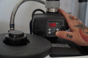
- Press the power button on the control unit, the pump will automatically start and begin pumping water.
- The screen will display the current pressure of the system. Please note, it may take a few seconds for pump to clear any airt locks and begin pumping water.
- Close all of the outlets, the pump will continue to run as the standing pressure increases on the system pipework.
- Once fully pressurised the pump will stop running.
- Check for leaks whilst the system is fully pressurised.
- Tank may flex slightly when fully filled and is built to accommodate this.
After commissioning the unit is ready to activate on demand when an outlet is opened.
Accessories
We have a range of accessories specifically designed for TankBoost, including drain-off plugs, inlet/outlet connectors and insulation jackets. The accessories are robust, reliable and compatible with TankBoost installations. Explore the accessories range here.
Linking Tanks
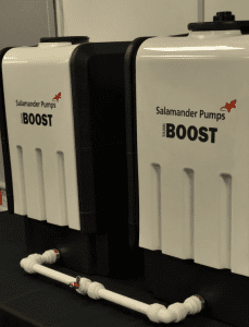
Depending on the water capacity required for the property, it may be beneficial to link a storage TankBoost to the primary TankBoost unit, to increase stored water capacity. Please refer to the TankBoost Installation Guide for more information regarding linking additional storage tanks. The capacity of water stored shouldn’t exceed what is required in any 24 hour period to prevent stagnation and any additional tank should be the same capacity as the primary unit. Please note that only one pumped unit is required.
TankBoost CAT5
If there is potential for hazardous fluids to be used, a Category 5 tank is required by the Water Regulations to protect against backflow, as Category 5 fluids pose serious health risks.
TankBoost CAT5 offers the same mains boosting solution, with the additional feature of its type AB air gap, a non-mechanical backflow prevention arrangement, making it suitable for category 5 fluid applications.
As with the standard models of TankBoost, CAT5 models are also available in a range of sizes and in a 3.0 Bar variant delivering up to 80 L/min and a 5.0 Bar variant delivering up to 120 L/min.
For specification advice or further installation support, please call us on 0191 516 2002.