No. The warranty on your replacement pump is carried over from your original purchase and starts from the date you purchased the original product.
Yes. You will receive an email confirmation following submission of an online warranty registration.
If you are a Merchant wishing to return a pump please contact our Sales Department by calling 0191 5162002 or email sales@salamander pumps.co.uk.
If you are an Installer / Householder please contact our Technical Team on 0191 5162002, or tech@salamanderpumps.co.uk.
Please confirm your product model and serial number.
Please contact our Sales Team via email sales@salamanderpumps.co.uk and we will arrange for one of our Business Development Managers to contact you directly to explain the process of opening a direct account with Salamander Pumps.
Many homes suffer with low water flow. This can be caused by a number of factors, including inadequate mains water supply, restrictive pipework, collapsed mains water pipe, and restrictive outlets.
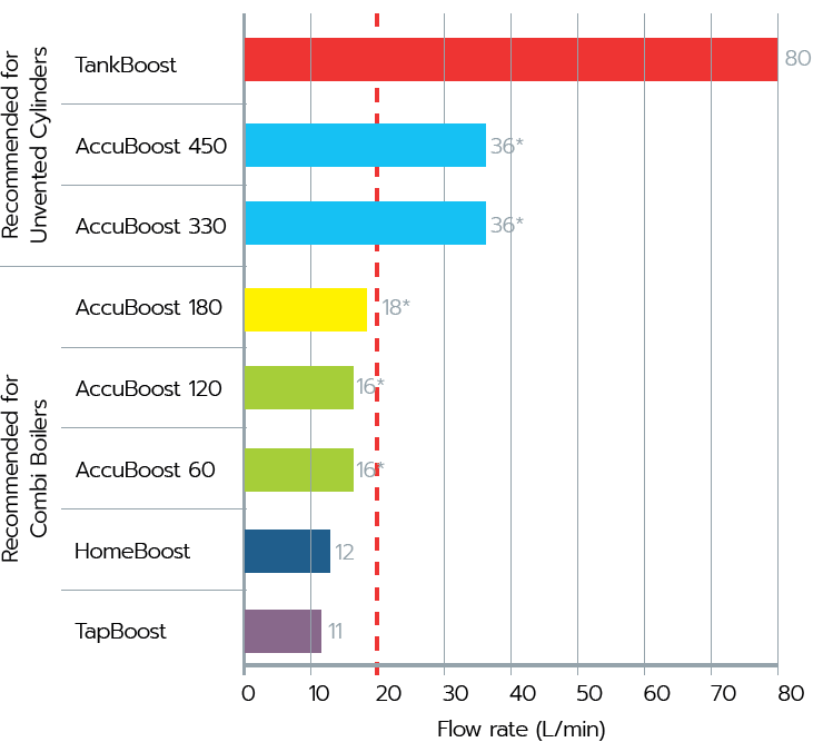
There are many solutions available that will increase the water flow in a property. The example below illustrates how the Salamander Pumps MainsBooster range can provide a boost to water flow rates. View the full range on the Salamander Pumps website.
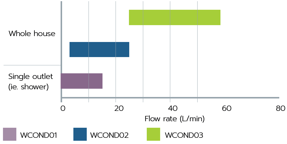
Example: A property currently has a total incoming water flow rate of 20L/min and an unvented cylinder but cannot run all showers at the same time without the flow dropping off.
The vertical red line on the graph indicates 20L/min. Salamander Pumps’ TankBoost, AccuBoost 450L or AccuBoost 330L will deliver more than 20L/min, with TankBoost delivering up to 80L/min. Increasing the flow rate will allow multiple outlets to be used at the same time.
*Assumes a natural mains flow rate of 12L/min in addition to the flow provided by the accumulator.
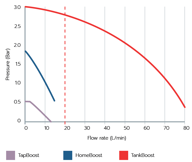
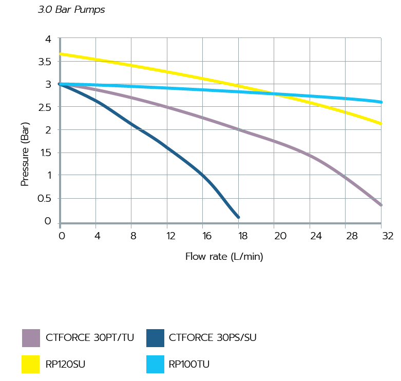
Many homes in the UK suffer with low water pressure, our range of products can offer a solution to overcome this. The graph below shows the pressure TapBoost, HomeBoost and TankBoost can deliver.
Example: A property currently has 1.0 Bar pressure at 20L/min but the water isn’t reaching the outlets on the top floor, so the taps are trickling and the shower doesn’t work at all.
The vertical red line on the graph shows at 20L/min flow rate, Salamander Pumps’ TankBoost will deliver 2.7 Bar pressure. Therefore by installing TankBoost the pressure is strong enough to boost the water to the outlets on the top floor.
Gravity fed systems are still widely used in homes across the UK, they rely on gravity to push water around the system, which often isn’t forceful enough for powerful showers or flowing taps.
The pumps in Salamander Pumps’ GravityBooster range will improve the pressure in these systems, whether you need to boost water pressure for a single shower or tap, multiple outlets in the bathroom, or throughout the entire house.
Yes, the water company obligation is to provide 9 L/min and 0.7 bar where the communication pipe from the mains water supply ends, normally at the water meter. The homeowners responsibility comes within the individual property boundary.
If the flow rate is insufficient and is not adequate to meet the demand for water in the property, our products can help. For example, combination boiler and unvented hot water cylinders require more than 9 L/min to operate, HomeBoost will provide up to 12 L/min suitable for small combination boilers. However, an unvented cylinder requires more than 20-22 L/min, which can be provided by the AccuBoost (330/ 450 Unvented) or TankBoost (350 & 450) units.
Typically if you have a cold water storage tank in the loft space and a hot water cylinder in an airing cupboard, you will have a conventional open vented Gravity fed system. The water is heated either directly by an immersion or indirectly by a boiler. Mains fed systems can include a combination boiler, typically a wall mounted unit where cold water is heated on demand. An unvented system is a pressurised cylinder (unvented) fed and pressurised by the incoming mains, the stored contents are heated (various methods) and hot water pushed out by the force of the incoming mains on demand.
The flow rate of a pump basically tells us the flow of water it can move in a given time. This is shown as LPM or L/M which is basically the litres of liquid moved in one minute.
All Salamander shower pumps are supplied with a fused 3 pin plug. Pumps can be hard wired into a fused spur without invalidating the warranty.
TankBoost does not come with a 3 pin plug.
If you live in an older property, there is a good chance you have a gravity fed system. Renowned for poor water pressure and flow.
A gravity fed system consists of a large cold water storage tank usually located in the loft and a hot water cylinder located in an airing cupboard. These systems rely on gravity to force water around the system, with the height of the cold-water storage tank determining the pressure throughout the system.
Cold water is delivered to a cold-water storage tank from the water mains. Cold water from the cold-water storage tank is then supplied to the outlets around the system, such as taps, toilets, showers and baths. Once an outlet requiring hot water is opened, gravity will force cold water from the cold-water storage tank into the hot water cylinder, this will then force hot water out from the top of the cylinder, delivering hot water to the open outlet.
A shower pump is a device that boosts water pressure in your pipes by increasing the volume of water which is pumped through them. The improved water pressure is visible at the showerhead where the force of the spray increases as the pressure and flow rate become stronger.
Shower pumps are designed to improve the water pressure in a gravity fed system by increasing the volume of water which is pumped through the pipes. We manufacture two types of pumps which work in slightly different ways.
Regenerative shower pumps, such as our CT Xtra, CT Bathroom and CT Force ranges, have a water wheel impeller inside the end of the pump. Water enters the shower pump through the inlet, the impeller spins the water around inside the impeller casing, building pressure as the water travels around the end of the pump. Between the inlet and the outlet of the shower pump there is a stripping block, this strips the water from the impeller and directs the water out of the top of the pump.
Our ORA and Right Pump ranges are centrifugal pumps. To increase the water pressure in a system these pumps utilise centrifugal force. Water enters through the inlet on the end of the shower pump, filling the impeller chamber and the impeller. As the impeller spins, water is forced outwards using centrifugal force, this builds higher pressure within the chamber which thrusting water out the top of the pump.
This method of increasing pressure results in a higher flow efficiency than with a regenerative shower pump, so installations with multiple bathrooms can benefit from installing a centrifugal pump. There is also no need to strip the water from the impeller as centrifugal force directs the water out of the pump, this makes centrifugal pumps quiet.
To successfully activate the pump on first operation: Connect the pump to the pipework, turn on incoming water supply and ensure that all isolating valves are open. Open an outlet and check for natural flow. Ensure all air is purged from the system and inspect connections and connecting pipework for leaks. Plug in electrical supply to pump and turn on. The flow will now increase as the pump activates. Close the outlet fully and the pump will stop.
The Customer Support section offers guidance on pre installation, installation and post installation enquiries, including FAQs, videos, downloads and articles. For support relating to your product’s warranty, visit the Warranty Support section, where you can request a replacement product, site survey or a service engineer visit.
We offer a range of accessories that will ensure a smooth installation, protect the products from damage caused by aeration, dry running, excessive temperatures and can help to dampen noise.
You can view the all available accessories on our shop.
Visit the downloads page to access all of Salamander Pumps downloadable content, including brochures, installation manuals and datasheets.
We have a range of training tools including:
We’ve engineered our pumps to be some of the quietest in the UK. CT Xtra, CT Force, HomeBoost and Right Pumps have been independently tested against competitor products and so we can officially say that we have some of the quietest pumps on the market, and have been awarded the Quiet Mark. It is worth mentioning that there is some noise associated with the operation of all of our products.
The table below shows the warranty periods for each of our products:
Range | Product | Duration |
---|---|---|
GravityBooster | Ora | 1 years warranty |
GravityBooster | CT Xtra | 3 years warranty |
GravityBooster | CT Bathroom | 3 years warranty |
GravityBooster | CT Force | 5 years warranty |
GravityBooster | Right Pump | 3 years warranty |
MainsBooster | TapBoost | 1 years warranty |
MainsBooster | CombiBoost | 1 years warranty |
MainsBooster | HomeBoost | 3 years warranty |
MainsBooster | AccuBoost | 3 years warranty |
MainsBooster | TankBoost | 2 years warranty |
Our Technical Team are available –
Mon to Thurs: 8.00am-4.30pm
Fri: 8.00am – 2.30pm
We offer a range of support outside these hours from our customer support area.
We want to make getting in touch with us as easy as possible. So, have a range of resources available to help you including troubleshooting articles, FAQs and videos.
If you need further support, you can contact us via one of the following methods. If you’re contacting us about a pump in your home, please make sure you have your serial number to hand before you call us.
Low water pressure can be caused by poor natural head on a gravity system, or an increase in demand ie if more than one outlet is used at the same time, or an extension/ new bathroom etc has been added to a property. On mains fed systems, water pressure will vary throughout the day and at peak demand times a drop in performance may be noticed. Other contributors to low water pressure may include poor plumbing or blocked pipework, blocked filters, bent AV Couplers/ hoses and air in the system.
The water pressure can vary when the hot and cold water are supplied in different ways, such as when the hot water is supplied by a gravity fed system and the cold water is supplied directly from the mains. This can be seen when running a mixer tap and the pressure of the mains fed cold water is fine, but the gravity fed hot water pressure is poor.
It is possible to overcome this by using a universal, single ended pump to improve the gravity fed hot water pressure. If the hot water is supplied via a hot water cylinder, check for any blockages or restrictions in pipework that could be effecting the performance.
Our range of water boosting solutions offer a solution to low water pressure and/or flow.
If you have a gravity fed system, installing a shower, bathroom or whole house pump from our GravityBooster range can resolve the low water pressure in the home.
If you have a mains fed system, such as a combination boiler or an unvented cylinder, one of our MainsBooster inline pumps or accumulator products will improve the water pressure and flow.
If you suffer from poor water pressure in your home one of our products can offer the perfect solution to boosting water pressure and/or flow. The results are: improved shower performance, quicker bath fill and strong flowing taps.
However, it is important to make sure that you get the right pump for your system. Use our product selector to help you find the right product.
Depending on the type of pump you have the serial number will be on a label attached to the top of the pump, on the vessel attached to the top of the pump, or on HomeBoost and CombiBoost it will be on the underside of the pump.
You can also find the serial number on a sticker on the back of your installation manual.
Please ensure that you have your product serial number to hand before contacting us about an existing pump installation.
We regularly receive queries from customers who are concerned that their pump has already been used because they find water inside the pump while unboxing it. However, the quality testing carried out before our products leave the factory means that they may contain water upon purchase.
The AGL (anti-gravity loop) is a U-bend in the hot pipe supply created by dropping the pipe down 400mm before rising up again. The AGL prevents air in the system tracking up into the pump chamber and prevents back siphoning of water away from the pump which can cause aeration issues.
If the pump is above the dome of the hot water cylinder, we would advise using a side entry No-Stop Essex flange and AGL.
Yes, TankBoost is ideal for delivering pressure and the higher flow rates required to unvented systems up to 80 litres per minute. TankBoost can also be used to supply combi-boilers, however, combi-boilers may restrict the flow rate of hot water that can be produced.
The cold water storage capacity must be adequate for all household requirements. A minimum of 50 gallons of useable cold water is required for a full bathroom and a minimum 30 gallons for a shower or ensuite. If you are unable to install a larger cold water storage tank, you can link multiple tanks in 28mm pipework to achieve the required capacity (linked tanks should be sat at the same level). Where it is not possible to add additional cold water tanks, a Water starvation Protection Kit (WSP) can be used. This unit will give automatic protection to the pumps by switching off the power to the pumps when the water in the supply tank falls below an acceptable level. (It is NOT a cure for insufficient cold water storage and 50% of the required water is required when using a WSP kit).
An easy way to understand the difference between flow is to remember pressure is the force exerted on water as it is pushed through your pipes to move it from one place to another, whilst flow is the volume of water passing through your pipes at any given time. Typically the larger the pipe is, the better the water will flow through it.
If you live in an older property, there is a good chance you have a gravity fed system. Renowned for poor water pressure and flow.
A gravity fed system consists of a large cold water storage tank usually located in the loft and a hot water cylinder located in an airing cupboard. These systems rely on gravity to force water around the system, with the height of the cold-water storage tank determining the pressure throughout the system.
Cold water is delivered to a cold-water storage tank from the water mains. Cold water from the cold-water storage tank is then supplied to the outlets around the system, such as taps, toilets, showers and baths. Once an outlet requiring hot water is opened, gravity will force cold water from the cold-water storage tank into the hot water cylinder, this will then force hot water out from the top of the cylinder, delivering hot water to the open outlet.
There are three main types of hot water system in the United Kingdom – gravity fed, mains fed: combination boiler, and mains fed unvented cylinder.
Gravity fed
Mains fed: Combi boiler
Mains fed: Unvented
Click here for more information on identifying your water system
A shower pump is a device that boosts water pressure in your pipes by increasing the volume of water which is pumped through them. The improved water pressure is visible at the showerhead where the force of the spray increases as the pressure and flow rate become stronger.
There are multiple factors that will impact which is the best shower pump for your home.
Use our product selector tool to find the right product.
A gravity fed water system is identified by a cold-water storage tank, usually stored in a loft, and a hot water cylinder. These systems rely on gravity to force water around the system, with the height of the cold-water storage tank determining the pressure throughout the system.
Cold water is delivered to the cold-water storage tank from the water mains. Cold water from the cold-water storage tank is then supplied to the outlets around the system, such as taps, toilets, showers and baths.
The cold-water storage tank also feeds the hot water cylinder, where a heating coil from the boiler or immersion heater will cause the cold water to become hot. Once an outlet requiring hot water is opened, gravity will force cold water from the cold-water storage tank into the hot water cylinder, this will then force hot water out from the top of the cylinder, delivering hot water to the open outlet.
It is common for gravity fed water systems to suffer with low pressure, installing one of our gravity fed shower pumps can help to improve the pressure, click here to see our range gravity-fed shower pumps.
Gravity-fed water systems are either positive or negative head. Before choosing a gravity-fed shower pump it is important to know whether your system is positive head of negative head, click here for further information.
If you’re unsure which product you need read our guide to selecting the right product, or use our product selector tool.
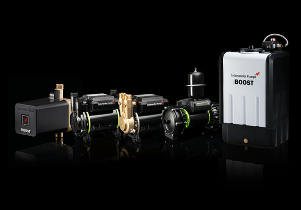
A mains fed system is one which is fed directly by the mains water such as a combination boiler or an unvented hot water cylinder.
A gravity-fed system is either positive or negative head. In a positive head system a water flow rate of at least 2L/min exists from gravity alone. In negative head systems the water flow rate is less than 2L/min.
When choosing which pump you need it is important to know if the system is positive or negative head as incorrect selection can mean the pump won’t work.
A positive head pump will only work in a positive head system and a negative head (universal) pump will work in both a positive and negative head system, so if you are not sure choose a negative head pump.
Click here to learn how to determine if your system is suitable for a positive head pump.
A positive head pump will activate when a minimum flow of water passes through the pump and out of the pumped outlet, such as a shower or tap, naturally (without assistance from the pump). The minimum flow rate required for our positive head pumps is 2 litres of water per minute (L/min).
You will need to measure the flow rate to determine if a positive head pump is suitable for your system. You will need to test all outlets, such as showers and taps, that are going to be pumped to determine if they have the required minimum flow rate of 2L/min. Watch our video to learn how to measure the water flow rate.
If you cannot measure the water flow rate, then you can check if the system is suitable for a positive head pump if there is more than 600 mm between the base of the cold-water storage tank and the highest point in the system after the pump.
If you are unable to achieve the minimum flow rate of 1 litre per 30 seconds from all outlets that are to be pumped you will need to install a negative (universal) head pump.
Measuring the water flow is an important step in choosing the right pump. Water flow rate is measured in litres per minute (L/min).
To measure the water flow rate, you will need a measuring jug and a timer.
For example, if you gathered 600ml in 10 seconds, to calculate the flow rate in litres per minute – 600 x 6 = 3600ML per minute = 3.6L/min.
You can also use our interactive flow calculator to work out the flow rate of a single outlet.
Learn how to measure your water flow from the video.
Shower pumps for a gravity fed system are either positive head or universal (negative head). When choosing the pump you need it is important to know if you need a positive head or universal (negative head) pump as incorrect selection can mean the pump won’t work.
A positive head pump is designed to assist and improve the natural flow of water. A flow switch set to activate positive head pumps when a flow rate of 2 litres per minute (L/min) passes naturally through the pump. Therefore, a minimum flow rate of 2L/min must be achieved naturally (without a pump) from all outlets in order to install a positive head pump.
A universal (negative head) pump works in a different way to a positive head pump. These pumps are capable of creating flow where there ordinarily isn’t a natural flow, such as loft conversion with outlets higher than the cold water tank or where ‘up and over’ pipework has been installed. Other considerations where a negative head pump may be needed include restrictive outlets such as a shower with body jets or an electric shower, or anywhere where mains fed cold water meets gravity fed hot water.
These pumps will pressurise the pipework between the pump and the outlet, which, when the tap or shower is turned on, releases pressure which a sensor in the pump sees and activates the pump. Once the outlet is turned off, the pump runs on for a short time and re-pressurises the pipework ready for the next time. A negative head pump usually has a pressure vessel, which acts as a buffer to stop false activation.
If you are unable to achieve the natural minimum flow rate from all outlets that are to be pumped for a positive head pump, you will need to install a universal (negative head) pump. A negative head pump activates when it detects a drop in pressure
All of the pumps available at Salamander Pumps are rated in ‘bar’, which is the measure of pressure – 1 bar pressure being equal to 10 metres static head of water (the pressure exerted by 10 metres of water).
The higher the bar rating, the higher the pressure. The following is a general guide for applications:
1.5 bar pressure for one shower, tap or appliance
2.0 bar pressure for two or three showers, taps or appliances or a bathroom
3.0 bar pressure for the whole house.
If you live in an older property, there is a good chance you have a gravity fed system. Renowned for poor water pressure and flow.
A gravity fed system consists of a large cold water storage tank usually located in the loft and a hot water cylinder located in an airing cupboard. These systems rely on gravity to force water around the system, with the height of the cold-water storage tank determining the pressure throughout the system.
Cold water is delivered to a cold-water storage tank from the water mains. Cold water from the cold-water storage tank is then supplied to the outlets around the system, such as taps, toilets, showers and baths. Once an outlet requiring hot water is opened, gravity will force cold water from the cold-water storage tank into the hot water cylinder, this will then force hot water out from the top of the cylinder, delivering hot water to the open outlet.
A shower pump is a device that boosts water pressure in your pipes by increasing the volume of water which is pumped through them. The improved water pressure is visible at the showerhead where the force of the spray increases as the pressure and flow rate become stronger.
A flange is a device that limits the amount of air entering a pump from the hot water cylinder. Air in the system is called aeration and it can cause problems such as fluctuations in water temperature, noisy pipework and in the case of the pump, damage to internal components. Fitting a flange will prolong the life of a pump, and for the Salamander Right Pump range a flange is a requirement of the installation to ensure a valid warranty. It is always best practice to fit a flange in any shower pump installation in a gravity fed system.
Shower pumps are designed to improve the water pressure in a gravity fed system by increasing the volume of water which is pumped through the pipes. We manufacture two types of pumps which work in slightly different ways.
Regenerative shower pumps, such as our CT Xtra, CT Bathroom and CT Force ranges, have a water wheel impeller inside the end of the pump. Water enters the shower pump through the inlet, the impeller spins the water around inside the impeller casing, building pressure as the water travels around the end of the pump. Between the inlet and the outlet of the shower pump there is a stripping block, this strips the water from the impeller and directs the water out of the top of the pump.
Our ORA and Right Pump ranges are centrifugal pumps. To increase the water pressure in a system these pumps utilise centrifugal force. Water enters through the inlet on the end of the shower pump, filling the impeller chamber and the impeller. As the impeller spins, water is forced outwards using centrifugal force, this builds higher pressure within the chamber which thrusting water out the top of the pump.
This method of increasing pressure results in a higher flow efficiency than with a regenerative shower pump, so installations with multiple bathrooms can benefit from installing a centrifugal pump. There is also no need to strip the water from the impeller as centrifugal force directs the water out of the pump, this makes centrifugal pumps quiet.
There are multiple factors that will impact which is the best shower pump for your home.
Use our product selector tool to find the right product.
Signs of low water pressure could be a sink or bathtub taking forever to fill, the shower might not be as powerful as you want, or your dishwasher could take longer to cycle than necessary.
If your natural water flow rate is less than 10 L/min then you will probably notice these signs. To check your water flow rate you can carry out a flow rate test.
Our products have been designed to offer a solution to low water pressure in the home. Find the right product for you by using our product selector.
A positive head pump will activate when a minimum flow of water passes through the pump and out of the pumped outlet, such as a shower or tap, naturally (without assistance from the pump). The minimum flow rate required for our positive head pumps is 2 litres of water per minute (L/min).
You will need to measure the flow rate to determine if a positive head pump is suitable for your system. You will need to test all outlets, such as showers and taps, that are going to be pumped to determine if they have the required minimum flow rate of 2L/min. Watch our video to learn how to measure the water flow rate.
If you cannot measure the water flow rate, then you can check if the system is suitable for a positive head pump if there is more than 600 mm between the base of the cold-water storage tank and the highest point in the system after the pump.
If you are unable to achieve the minimum flow rate of 1 litre per 30 seconds from all outlets that are to be pumped you will need to install a negative (universal) head pump.
Centrifugal pumps, such as our Right Pump range, use centrifugal force to increase water pressure within a system. Water enters through the inlet on the end of the shower pump, filling the impeller chamber and the impeller. As the impeller spins, water is thrown outwards using centrifugal force, this builds higher pressure within the chamber which forces water out the top of the pump.
This method of increasing pressure results in a higher flow efficiency than with a regenerative shower pump, so installations with multiple bathrooms can benefit from installing a centrifugal pump.
Regenerative shower pumps, such as our CT range of pumps, have a water wheel impeller inside the end of the pump. Water enters the shower pump through the inlet, the impeller spins the water around inside the impeller casing, building pressure as the water travels around the end of the pump. Between the inlet and the outlet of the shower pump there is a stripping block, this strips the water from the impeller and directs the water out of the top of the pump.
A positive head pump will activate when a minimum flow of water passes through the pump and out of the pumped outlet, such as a shower or tap, naturally (without assistance from the pump). The minimum flow rate required for our positive head pumps is 2 litres of water per minute (L/min).
If you don’t have this minimum flow rate from all outlets that are to be pumped, or if you’re not sure, then you will need a universal (negative head) pump.
A universal (negative head) is suitable for boosting water pressure in any gravity fed system. These pumps are activated by a drop in pressure in the system caused by an outlet being opened, such as tap or shower being turned on.
Positive head pumps are activated when at least 2 litres per minute passes through the pump, and are therefore activated by flow rather than pressure. All outlets that are to be pumped must receive the minimum flow of 2 litres per minute for a positive head pump to be used.
So in systems with little (less than 2 litres per minute) or no natural flow, a universal (negative head) pump will be required.
Twin pumps have two impellers and are designed to supply both hot and cold water to showers, bathrooms and whole house installations.
A flange is a device that limits the amount of air entering a pump from the hot water cylinder. When water is heated, or replaced within the hot water cylinder, air bubbles are formed and collect around the side or the top of the cylinder.
If you are installing a pump, you need to ensure these air bubbles are not drawn into the pump.
By installing a flange, these air bubbles are prevented from entering the pump, as the flange can draw water from deeper within the hot water cylinder, allowing the air to pass up and out via the expansion vent pipe.
There are various flanges available, including:
Salamander Pumps’ S-type flange and Warix flanges are both top entry, meaning that they connect onto the hot draw off connection on the dome of a standard hot water cylinder. On the S-type flange the side connection supplies the hot feed to the pump and the top connection to the open vent pipe, whereas on the Warix flange, the pump supply connection is taken from the top and the vent pipe from the side connection.
A no stop Essex flange is a side entry flange, which requires drilling into the side of the cylinder. This flange is best for when a pump needs to be situated above the hot water cylinder and provides an unrestricted hot water supply into the pump.
A side entry flange, such as a no stop Essex flange, is required in two circumstances:
Outside of these circumstances a top entry flange can be used.
Watch the video guide of step-by-step installation of a 22mm no stop Essex flange on a hot water cylinder.
Watch the video with the S-flange step-by-step installation.
Air in the water supply can make the pump noisy and can cause premature pump breakdown. Pump degradation will result in an eventual leak.
A flange installation is crucial for protecting the pump from damage caused by air. It maintains the longevity of your pump.
Fitting the flange is also required for Right Pump warranty.
Cavitation occurs when air, steam, or thermal fluid vapor accumulates in a fluid. When cavitation occurs, air bubbles continuously form and collapse (implode) in the liquid. This generates noise and can lead to damage in the installation. Air can damage the pump, so it is important to install a flange on the hot water cylinder.
Watch the video with step-by-step installation of a 22mm no stop Essex flange on a hot water cylinder.
Single impeller pumps supply either hot or cold water, to single or multiple outlets. This can often be when the cold water is mains fed and the hot needs to be boosted to match this pressure.
Air causes a range of problems in pumps and can ultimately damage or break the pump. The best way to prevent air getting into the pump is to ensure that a flange is fitted on the hot water cylinder. Salamander sell an ‘S’ flange, which is a device used to remove air intake from the hot water cylinder from where the pumps draws hot water. The ‘S’ flange sits on top of the hot water cylinder and will need to be installed by a competent and trained installer. Click here for further information on the S falnge.
Most of our pumps must have a flange fitted to ensure longevity of life of the pump and for the warranty to remain valid. Click here for further information and exceptions to this.
Please ensure that the pumps’ warranty and installation guide book is checked before pump installation.
If the pump is activating but there is still low/no pressure to the shower this is likely caused by a restriction after the pump, this could be:
Reasons why a positive head pump might not turn on:
If your pump is starting up on its own there are few things you need to consider.
First determine if you have a universal (negative head) pump. These pumps are easily identified by a pressure vessel on the top of the pump.
A universal (negative head) pump turn on when they recognise a pressure drop in the system. A dripping tap or leak in the system can cause the system pressure to drop which would activate a negative head pump, even though all outlets are turned off. This is called ‘hunting’. When a pump is ‘hunting’ you will hear the pump switch on for a few seconds when no outlets are open. Find out how to test if your pump is hunting.
A positive head pump doesn’t have a pressure vessel. These pumps are activated by a flow switch set to turn the pump when a natural flow rate (without assistance from the pump) of 2 litres per minute passes through the pump.
If you have a positive head pump that is turning on and off during use, this is most likely due to the water flow rate being insufficient to activate the pump.
To successfully activate the pump on first operation: Connect the pump to the pipework, turn on incoming water supply and ensure that all isolating valves are open. Open an outlet and check for natural flow. Ensure all air is purged from the system and inspect connections and connecting pipework for leaks. Plug in electrical supply to pump and turn on. The flow will now increase as the pump activates. Close the outlet fully and the pump will stop.
The most likely cause for a humming or buzzing noise is that the pump has seized. This will probably be because of one of two things:
Hot water – The installation guidelines recommend that the temperature of the water going through the pump shouldn’t be any higher than 60°C. This is because some of the components within the pump can be damaged by hot water.
Air – Excessively hot water bubbles, and generates air. Air can damage some of the components within the pump, particularly the impellers that drive the movement of the water. If they aren’t moving then the pump may seize and a humming noise will be heard.
If the pump is slow to switch on it could be because there is something restricting the flow of water. This could be:
When a shower pump starts to display any of the following, an ‘open-ended’ test can be carried out to check that each side of the pump is functioning as it should:
Low pressure on hot, cold or both sides of the pump
Hot, cold or both sides of the pump will not activate.
Watch our video to learn how to carry out the open-ended test.
When a shower pump starts to lose pressure or stops activating on hot or cold water, then turning the pump around can help diagnose the problem.
Watch our video on turning the pump around.
This is usually down to the natural flow of water, either the hot or the cold supply of water is not generating enough flow to activate the individual flow switches. Salamander Pumps require 2 litres per minute per side to switch on.
If this is a persistent problem it may mean that you need a universal pump. You can upgrade your shower pump to a universal shower pump by contacting Salamander Pumps.
Universal (Negative Head) Pump
If your pump has one of these (pressure vessel), then the most likely cause for the pump running is that there is a leak somewhere in the system (like a dripping tap or shower, or slow pipework leak somewhere in the system.)
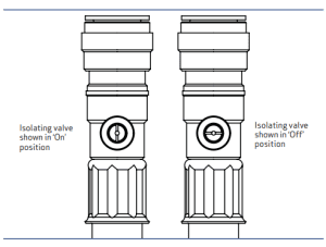
The easiest way to test if this is a pump issue or a leak, is to switch off water supply to the pump using the switches which are on the anti-vibration couplers (hoses) attached to the pump.
If after the valve is in the off position (on both ends of the pump if it’s a twin ended pump) the pump continues to run then it’s a pump issue and you need to contact our technical desk either by calling 0191 516 2002 or emailing: tech@salamanderpumps.co.uk
Positive Head Pump
If your pump doesn’t have a pressure vessel and is a positive head pump then use the isolative valves as shown above to switch the water to the pump off. If the pump turns off then there is a chance that water is going to somewhere in the system that it shouldn’t be e.g the vent pipe or cold water tank. If this isn’t the case then contact our technical desk either by calling 0191 516 2002 or emailing: tech@salamanderpumps.co.uk
If the pump is positive head (doesn’t have a pressure vessel) and is turning on and off during use, this is most likely due to the amount of water coming into the pump not being enough to make the pump kick in. Positive head require 2 litres per minute (L/min) per side to activate so it might be that the flow is stopping and starting. Watch our video to learn how to measure water flow rate – this will help to determine if the system has the necessary flow rates for a positive head pump.
A negative head (universal) pump is indicated by a pressure vessel (as shown in the picture). These pumps turn on when they sense a pressure drop in the system. A dripping tap or leak in the system can cause the system pressure to drop which would activate a negative head pump, even though all outlets are turned off. This is called ‘hunting’. When a pump is ‘hunting’ you will hear the pump switch on for a few seconds when no outlets are open.
An isolation test will help to determine if a leak in the system is causing the pump to hunt. Watch our video to learn how to carry out an isolation test.
If the pump turns on while the outlet isolating valves are turned off, then it could be down to low or no pressure in the pressure vessel. Watch our video to learn how to check the pressure vessel – you will need a flat head screwdriver, and a foot pump with a gauge to carry out the test.
When a shower pump starts to display any of the following, an ‘open-ended’ test can be carried out to check that each side of the pump is functioning as it should:
Watch our support video to learn how to carry out the open-ended test
A positive head pump requires a minimum flow rate of 2 litres per minute (L/min) to pass through the pump and out of the outlet, such as a tap or shower. 2L/min of both hot and cold water is required to turn on. If the flow rate is not at or above 2 L/min then the shower pump will not start. Click here to learn how to measure the flow rate.
Reasons why a positive head pump will not turn on:
Watch our video to learn what to do when a positive pump will not turn on.
Unfortunately, this usually means that the pump has seized. Please contact our technical team on 0191 516 2002 or email tech@salamanderpumps.co.uk for further advice.
Water around the pump doesn’t always mean that the pump is leaking, sometimes the leak is from the pipes that are above the pump so check those first.
If the leak is coming from the pump then please contact our technical support team on 0191 516 2002 or email tech@salamanderpumps.co.uk
An accumulator stores water at pressure. In an AccuBoost accumulator installation the water in the system is stored at the peak mains pressure.
A non-return valve (NRV) ensures that the built-up pressure in AccuBoost install is locked into the system. Without an NRV the system pressure would fluctuate with the mains pressure.
The NRV also prevents water in the system from flowing back into the mains supply.
Using a HomeBoost fittings kit will ensure smooth and efficient installation. The kit includes high quality brass connectors and an isolating valve to ensure easy servicing, with the connectors designed to allow the pump to easily slide out when required.
Signs of low water pressure could be a sink or bathtub taking forever to fill, the shower might not be as powerful as you want, or your dishwasher could take longer to cycle than necessary.
If your natural water flow rate is less than 10 L/min then you will probably notice these signs. To check your water flow rate you can carry out a flow rate test.
Our products have been designed to offer a solution to low water pressure in the home. Find the right product for you by using our product selector.
The TapBoost pump is IPX4 rated and the power supply unit is IPX0 rated. The power supply unit and plug must be protected from water and moisture. Please refer to the installation manual for more information.
Despite its name, TapBoost can be used for various poorly performing outlets. Examples include (but are not limited to) toilet cisterns, kitchen appliances and some electric showers (please refer to the *installation manual* for more info regarding the limitations when it comes to electric showers).
TapBoost is designed to boost the water flow rate rather than pressure. TapBoost does provide an increase in pressure, but this is dependent on incoming pressure.
A minimum natural flow rate of 1.2 L/min from the outlet is required for TapBoost to activate.
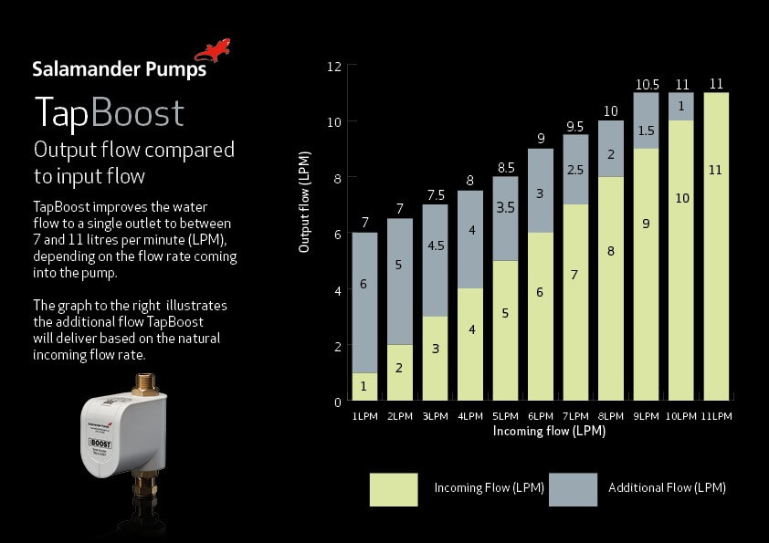
Unlike HomeBoost which adjusts its speed to continuously deliver 12 L/min, TapBoost runs at a constant speed. This means that the boosted flow is dependent on the incoming natural flow. For example:
When the incoming natural flow is 1.2 L/min TapBoost will boost the flow to up to 7 L/min.
When the incoming natural flow is 4 L/min it will boost the flow to 8 L/min.
The graph below gives full details of what boosted flow can be expected given the incoming flow.
When the incoming natural flow reaches 11 L/min, TapBoost will go into idle mode and stop boosting the flow to ensure it is never pumping more than 12 L/min, remaining in line with the Water Regulations.
The temperature of the water passing through TapBoost pump should be between 4°C – 60°C. Temperatures outside of this range may cause damage to the pump.
TapBoost operates at 34dBA. Learn more about TapBoost and other products from Salamander Pumps MainsBooster range.
TapBoost should never be installed to restrictive or collapsed pipework or supply, such as a lead main.
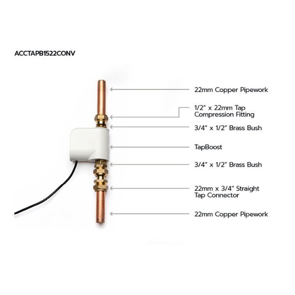
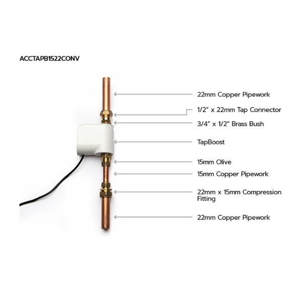
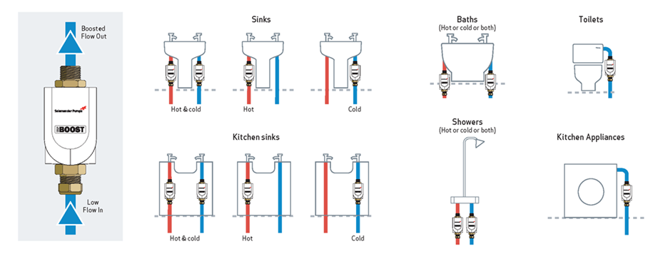
TapBoost can be installed on a shared main provided that it is only being used to boost a single outlet within one property, as highlighted by the typical installations image.
TapBoost can be installed on a hot or cold outlet in a gravity-fed system. However, there must be a minimum natural flow of 1.2 L/min from the outlet to be boosted.
TapBoost can be installed in combi boiler systems to boost either a hot or cold outlet.
TapBoost cannot be installed on hot water pipes/outlets from an unvented system – TapBoost should only be fitted to a cold-water outlet in unvented systems.
There must be a minimum natural flow of 1.2 L/min from any outlet to be boosted.
Yes. TapBoost can be installed in certain zones within a bathroom, however the plug/power supply must be outside of the bathroom and the installation must adhere to the latest I.E.E. electrical regulations. Refer to the installation manual for more information.
TapBoost is not suitable for boosting multiple outlets.
If multiple outlets suffer with poor performance in a mains-fed system a larger inline pump or accumulator tank should be installed – click here to view our full MainsBooster range.
When more than one outlet suffers with poor water performance in a gravity-fed system then a bathroom or whole house pump should be installed – click here to view our full GravityBooster range.
Yes, however there must be sufficient natural flow/pressure to allow the electric shower to operate before installing a TapBoost. Please note, many electric showers are restrictive by their nature, and you should check with your electric shower manufacturer to see if the maximum flow rate from the shower is already being achieved.
Yes, TapBoost can be used to boost outlets providing drinking water such as kitchen taps.
TapBoost can be used on communal supplies provided that it is only being used to boost a single outlet within one property, as highlighted by the typical installations image.
TapBoost can be installed horizontally or vertically however for optimum performance it is better fitted vertically. Never install TapBoost upside down or against the direction of flow.
No, two TapBoost pumps in-line will not deliver double the flow and TapBoost must not be installed in this way. If a single TapBoost does not provide adequate flow, please consider one of our other products:
Our MainsBooster range features larger inline pumps and accumulator tank which will provide greater flow rates in mains-fed systems.
Our GravityBooster range includes pumps which will deliver higher flow rates in gravity-fed system
TapBoost should be fitted as close to the poorly performing outlet as possible. Correct installation is essential for safe operation and a trouble free system. It is therefore important to read “Installation and warranty guide for TapBoost” thoroughly and ensure you comply with it.
Yes. The power pack and cables supplied with TapBoost must be used to power the pump. The supplied power pack and cables have been certified for use with TapBoost to ensure that they comply to the UK safety standards. The use of other power packs will invalidate the warranty.
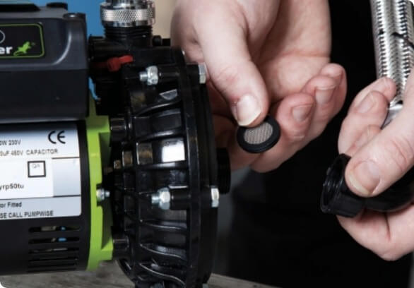
Yes, the filter prevents debris and foreign objects entering the pump. Should the filter become blocked it can be removed for cleaning and then replaced. A spare filter is also provided in the box.
TapBoost is supplied with a filter pre-fitted to the inlet and a spare filter in the box. The flat face of the filter should be inserted into the inlet port until the flat face sits flush with the pipe stop.
TapBoost has a 15mm compression fitting on the inlet and a ½” BSP male connection on the outlet. Learn more from “Installation and warranty guide for TapBoost“.
TapBoost has a 15mm compression fitting on the inlet to allow installation directly onto pipework. The outlet has a ½” BSP male thread allowing any suitable connection to be attached. When installed on mains water applications, no detachable hose sets should be used. If a flexible hose is used for connection to a gravity fed system, it should be no longer than 300mm.
The 15mm compression fitting on the inlet allows TapBoost to be installed directly onto pipework and the ½” BSP male connection allows flexibility for TapBoost to be installed in a range of applications, allowing TapBoost to be adaptable depending on the installation requirements.
The TapBoost power supply unit has a green LED which will illuminate when there is power to the supply unit.
The TapBoost pump is fitted with a blue LED to indicate its status. The image shows the location of the LED.
When the pump is in ‘standby mode’ (electrical supply to the pump but the outlet is not open) the LED will remain solid for 5 minutes. After 5 minutes the LED will turn off, but the pump will remain in ‘standby mode’.
A fast-flashing LED indicates that the pump is in ‘boosting mode’ (outlet is open and TapBoost is boosting the flow).
When the outlet is closed, TapBoost will then enter ‘standby mode’ where the LED will remain solid for 5 minutes as described above.
TapBoost intelligently monitors the flow of water. If the flow reaches 11 lpm or more, it will enter ‘idle mode’ indicated by a slow pulsing blue LED. The pump continues to monitor the flow but will not provide any additional boost. If the flow drops below 11 lpm, the pump will again switch to ‘boosting mode’ indicated by a fast-flashing blue LED.
Blocked filters can make our products slow to activate and water to become less powerful. Cleaning the filters can resolve these issues.
All pumps will make some noise, as water is being moved at a high speed and being thrust out of a pump. Depending on the type of pump, water will be moved in different ways and therefore different pumps can make noises.
If the HomeBoost pump is making an unusual noise, it is worth checking the installation is correct and eliminate contributing factors to the operational noise such as transfer noise:
First check to see if there is a green light on the transformer unit.
If there isn’t then:
If there still isn’t a green light, then the power cable will need to be replaced so please call us on 0191 516 2002.
If the green light is illuminated on the powerpack but the TapBoost still isn’t activating then please check to see if the blue light on the top of the pump is lit.
If it isn’t:
If the TapBoost still isn’t activating then you need to call us 0191 516 2002.
If the blue light is illuminated then please check the flow rate to the outlet, you can find details of how to do that here.
If your flow rate is more than 1.2L/min and the pump still isn’t activating then please call us on 0191 516 2002.
If your flow rate is less than 1.2 L/min then TapBoost won’t work as it needs this minimum flow rate to activate the pump.
In normal operation TapBoost is relatively quiet so if it has become noisy it could be because one of the following:
If TapBoost continues to run when the outlet is closed please check the following:
If this doesn’t solve the problem then there may be an issue with the pump, so please call us on 0191 516 2002.
We have designed our products to be as quiet as possible, but it is worth noting that there is some noise associated with the operation of our products. HomeBoost operates at 46dBA and has been awarded the Quiet Mark for being amongst the quietest in its category.
If you think your HomeBoost is noisier than it should be carry out the following –
If the pipework supplying the HomeBoost intelligent mains booster pump pump isn’t secured properly, the vibrations from the pump may cause it to rattle. Make sure that the pipework is clipped.
Learn more from the Pump installation and warranty guide for CombiBoost and HomeBoost.
First, check the power supply to the pump.
Then check the natural flow of mains water is sufficient to activate the pump.
In compliance with the Water Supply (Water Fittings) Regulations 1999, our range of inline pumps will not pump water if the natural mains flow rate is greater than 12 L/min.
No, TankBoost has been designed for cold water only, it can however be used to increase cold water flow rates and pressure to any mains hot water system such as unvented cylinders and combi boilers.
The AccuBoost is supplied as a ready to install unit. It is supplied with an upstream kit which includes a double check valve, inline strainer and a pressure reducing valve.
It’s impossible to say what flow rate will be delivered from the outlet as aspects of the system, such as the size of pipe work and how restrictive the outlet is, will impact the flow rate delivered from the outlet.
See ‘What are the flow rates from each accumulator in an open-ended test?’ for the flow rates delivered directly from the accumulator, excluding system factors.
An open-ended test measures the flow rate delivered directly from the accumulator and excludes any aspects of the system which might impact the flow rate.
The table below shows the maximum additional flow rates, in litres per minute (L/min) of each AccuBoost accumulator.
AccuBoost 60L | AccuBoost 120L | AccuBoost 180L | AccuBoost 330L | AccuBoost 450L |
4L/min | 4L/min | 6L/min | 24L/min | 24L/min |
A flow restrictor kit is available adapt the factory set flow rates. The flow restrictors will either:
Increase the flow, which will reduce the time AccuBoost will provide boosted water.
Decrease the flow, which will increase the time AccuBoost will provide boosted water.
At least 10cm of clear space is required around the tank and pump for maintenance access.
An AccuBoost accumulator must be installed in a dry location, protected from temperatures below 4°C and greater than 35°C, such as a kitchen cupboard, garage, loft space or outbuilding.
The vessel within the accumulator vessel is rated up to a maximum of 8.6 bar, therefore, to ensure safety and minimise damage a pressure limiting device must be installed, this is included with AccuBoost accumulators.
An AccuBoost accumulator stores both air and water within the vessel. The accumulator’s capacity is shared 50% air and 50% water, therefore a 450L accumulator will store approximately 226.5 litres of water.
The volume of water stored in the accumulator will vary depending on the pre-charge pressure held in the bladder of the vessel.
An AccuBoost accumulator vessel can be installed in a system with an incoming mains pipe in any material.
If the system has a high pressure (over 2.0 bar) but has a restricted main, then AccuBoost accumulator may still offer a solution – contact us for more information.
A sign of a restricted mains supply pipe would be a high standing pressure and low flow rate.
In systems with a natural mains flow rate below 12L/min the water vessel will take a long time to fill, installing a pump will ensure that the vessel will be filled more quickly.
An accumulator tank stores water under pressure to provide an excellent solution for properties requiring additional boost to mains water flow and pressure
No, TankBoost has been designed for cold water only, it can however be used to increase cold water flow rates and pressure to any mains hot water system such as unvented cylinders and combi boilers.
It’s impossible to say what flow rate will be delivered from the outlet as aspects of the system, such as the size of pipe work and how restrictive the outlet is, will impact the flow rate delivered from the outlet.
See ‘What are the flow rates from each accumulator in an open-ended test?’ for the flow rates delivered directly from the accumulator, excluding system factors.
An open-ended test measures the flow rate delivered directly from the accumulator and excludes any aspects of the system which might impact the flow rate.
The table below shows the maximum additional flow rates, in litres per minute (L/min) of each AccuBoost accumulator.
AccuBoost 60L | AccuBoost 120L | AccuBoost 180L | AccuBoost 330L | AccuBoost 450L |
4L/min | 4L/min | 6L/min | 24L/min | 24L/min |
A flow restrictor kit is available adapt the factory set flow rates. The flow restrictors will either:
Increase the flow, which will reduce the time AccuBoost will provide boosted water.
Decrease the flow, which will increase the time AccuBoost will provide boosted water.
It is rare that a system would have these measurements. These results may be caused by a restrictive mains pipe, such as a lead main. In this circumstances contact Salamander Pumps for advice.
A restrictive outlet may also give these results. Therefore, when checking the flow rate, you should open multiple outlets to get the most accurate measure.
For example, turn on two taps and the shower so they are fully open. While all are turned on, measure the number of litres per minute you get from all three outlets. Then combine the results together, this tells us the flow rate coming into the property –
Outlet | Flow rate (litres per minute) |
Shower | 6 |
Tap 1 | 2 |
Tap 2 | 2 |
Total flow rate | 10 |
In this example the flow rate is still below 12 litres per minute, therefore TankBoost is required.
No. To prevent stagnant water and debris build up the accumulator vessel must be installed vertically.
For the best performance we advise that the tank is installed as close as possible to the pump, which must be installed within 5m of the point of entry for the mains water, however there is no maximum distance between the tank and pump.
An accumulator stores water at pressure. In an AccuBoost accumulator installation the water in the system is stored at the peak mains pressure.
A non-return valve (NRV) ensures that the built-up pressure in AccuBoost install is locked into the system. Without an NRV the system pressure would fluctuate with the mains pressure.
The NRV also prevents water in the system from flowing back into the mains supply.
An AccuBoost accumulator vessel can be installed in a system with an incoming mains pipe in any material.
If the system has a high pressure (over 2.0 bar) but has a restricted main, then AccuBoost accumulator may still offer a solution – contact us for more information.
A sign of a restricted mains supply pipe would be a high standing pressure and low flow rate.
Yes, more than one accumulator can be installed into a system. Installing multiple accumulator tanks creates a greater stored water capacity and a higher flow rate (L/min).
AccuBoost accumulator systems have no maximum stored water capacity, however, please ensure adequate water turnover to prevent water stagnation.
In systems with a natural mains flow rate below 12L/min the water vessel will take a long time to fill, installing a pump will ensure that the vessel will be filled more quickly.
The pre-charge pressure is the air pressure stored within the bladder of the vessel. The air in the vessel is compressed by the water pressure, which pushes the extra volume of water out of the vessel. AccuBoost accumulators require that the pre-charge pressure is 1.5 bar less than the pressure of the incoming mains.
In AccuBoost accumulator installations, the minimum pressure of the mains must be 2.0 bar so that the vessel can be set to 1.5 bar below (0.5 bar). If the vessel is set to 0 bar then the positive impact of the accumulator is negated.
An accumulator vessel is a pressurised vessel. To allow the incoming mains water to be able to force water into the vessel, the pressure within the vessel must be lower than the pressure of the incoming mains.
For AccuBoost accumulators, the pressure within the vessel should be 1.5 bar below the pressure of the incoming mains. This size of pressure difference ensures that the incoming mains can fill the vessel and that there is enough pressure to force the water out of the vessel and to the outlet.
In AccuBoost accumulator installations, the minimum pressure of the mains must be 2.0 bar so that the vessel can be set to 1.5 bar below (0.5 bar). If the vessel is set to 0 bar then the positive impact of the accumulator is negated.
Legionnaires’ disease is caused by legionella bacteria. The bacteria may grow when conditions are favourable, therefore it’s important to control the risk by introducing appropriate measures. More information can be found at Legionnaires’ disease. The control of legionella bacteria in water systems.
We offer a range of vessel sizes in our AccuBoost range so the capacity of the vessel should match the usage of the property, ensuring adequate replenishment of the water.
It’s impossible to say what flow rate will be delivered from the outlet as aspects of the system, such as the size of pipe work and how restrictive the outlet is, will impact the flow rate delivered from the outlet.
See ‘What are the flow rates from each accumulator in an open-ended test?’ for the flow rates delivered directly from the accumulator, excluding system factors.
An open-ended test measures the flow rate delivered directly from the accumulator and excludes any aspects of the system which might impact the flow rate.
The table below shows the maximum additional flow rates, in litres per minute (L/min) of each AccuBoost accumulator.
AccuBoost 60L | AccuBoost 120L | AccuBoost 180L | AccuBoost 330L | AccuBoost 450L |
4L/min | 4L/min | 6L/min | 24L/min | 24L/min |
A flow restrictor kit is available adapt the factory set flow rates. The flow restrictors will either:
Increase the flow, which will reduce the time AccuBoost will provide boosted water.
Decrease the flow, which will increase the time AccuBoost will provide boosted water.
If you’re following on from our FAQ ‘Why is the pump on the accumulator running on/won’t turn off?’, you need to open the isolation valves on the outlet hoses and the tank connector hose before carrying out these steps.
To check the pre-charge pressure, first drain the tank, then close the inlet.
Next open all outlets in the property until no more water is comes out or it trickles out. Remove the black cap on the top of the vessel, revealing the Schrader valve. Place a pump with a pressure gauge, such as a bicycle pump, on the Schrader valve and check the pressure. If the pressure is less than 1.5 bar, increase it to 1.5 bar using the pump. If it is already 1.5 bar, contact Salamander Pumps.
First check that the pump is powerful enough for what you’d like to do. Each shower you want to run will require 1 bar pressure, so if you’d like to run two showers at the same time you’ll need a two bar pump. If multiple showers are being used at the same time, then a drop in performance may occur if the pump is undersized.
Ensure the flow rate is not reduced by keeping AV couplers as straight as possible to prevent starvation. Blocked filters may also reduce the flow and cleaning them may be a quick fix to improving flow rates.
The TankBoost additional storage units are supplied with a tank connection kit. This allows the additional storage unit to be connected to a primary TankBoost unit.
Yes! The tank is made from WRAS approved materials and components and is suitable for storing and pumping potable water. However, we strongly recommend taking a draw off to a drinking tap before the feed into the TankBoost unit to ensure access to potable water isn’t interrupted at any point e.g. in the event of a power cut.
A Type AB air gap is a non-mechanical backflow prevention arrangement comprising of an inlet, receiving tank and unrestricted weir overflow (rectangular or non-circular).
A weir air gap (Type AB) is needed to stop contaminated water mixing with the mains water and sits directly below the water discharge point.
TankBoost CAT 5 water tank features an air gap between the inlet and outlet to ensure that the water in the tank or cistern does not flow back into the mains supply.
Cat 5 water tanks are suitable for laboratories, chemical cleaners/contractors, butchery and meat trades, healthcare premises, abattoirs, dog grooming parlours, bin wash down areas for flats etc.
All the examples above carry the highest risk level of the most serious health hazard because of the presence of pathogens and radioactive or very toxic substances.
TankBoost CAT 5 water tank features an air gap between the inlet and outlet to ensure that the water in the tank or cistern does not flow back into the mains water supply.
Fluid Category 5 (CAT 5) is characterized as a hazardous fluid due to its high concentration of pathogenic organisms, radioactive elements, or extremely toxic substances. This classification encompasses fluids containing faecal matter, human waste, animal waste, or pathogens from various origins, all of which pose significant health risks.
TankBoost CAT 5 satisfies the applicable requirements of Water Regulations for Category 5 systems. TankBoost CAT 5 is fitted with type AB backflow protection, making it suitable for use where there is a risk of backflow contamination with fluid Category 5.
A Category 5 water tank features an air gap between the inlet and outlet, preventing any backflow of water from the tank or cistern into the mains water supply. These air gaps are Type AB which satisfies the applicable requirements of Water Regulations for Category 5 systems.
TankBoost CAT 5 is the mains water booster system is fitted with type AB backflow protection, making it suitable for commercial use where there is a risk of backflow contamination with fluid Category 5.
An unvented cylinder relies on the pressure and flow supplied by the incoming mains water and requires approximately 20 – 22 L/min to operate. If the mains fed water system is not supplying the necessary flow and pressure, TankBoost can be installed to increase the water performance.
TankBoost may also be needed if the pressure and flow is not adequate to meet the demand for water in the property.
If fitting TankBoost before an unvented hot water cylinder you still need to use the pressure reducing valve. We would always recommend following manufacturer’s instructions when installing in an unvented hot water system.
Unlike an AccuBoost, you do not need to fit a pressure reducing valve prior to the unit. For full installation requirements, consult the “Installation and warranty guide for TankBoost range“.
No. The TankBoost has a 8L pressure vessel pre-charged at 1.5 bar already supplied and fitted.
No, the pressure is fixed – up to 3.0 bar.
TankBoost will deliver up to 80L/min and up to 3.0 bar. This offers a solution for properties where there is a requirement for high flow rates and multiple outlets will be used at the same time, e.g. gym or bigger houses with multiple floors and outlets.
No. The same pump is used in all units and is capable of delivering up to 80L/min and up to 3.0 Bar. The size of the TankBoost relates to the capacity of stored cold water, i.e. a TankBoost 450L will hold 450 litres of useable cold water.
The TankBoost is for cold water only. Ensure that the stored volume of water remains above 4°C and below 20°C to avoid any bacterial growth and to protect the unit from frost.
Note: Insulation may need to be applied to the outside of the tank to achieve this.
No, there is no minimum flow requirement for filling the TankBoost. However, a restricted water main (i.e. lead) will increase the time taken to replenish the tank. If you have a poor natural flow of mains water into your property (less then 12L/min) you could use different products alongside TankBoost. For example, HomeBoost can be installed before TankBoost to boost the incoming mains water supply up to 12L/min.
If you think there is an issue with the pump in the TankBoost unit, please contact Salamander Pumps technical team on 0191 516 2002 for support.
All the requirements are outlined in the installation guide. You can also contact our tech team to make sure that TankBoost has been installed correctly.
No, you don’t need unvented ticket to install the TankBoost.
The outlet connection on all TankBoost units is 1″ BSP Female (inlet on all units 1/2″ BSP Male).
The floor/mounting surface (supporting TankBoost) must be flat and level, fully supporting the unit. It must be able to withstand the maximum full weight of the TankBoost unit (please refer to the technical specification for the weights of each unit). Additional supports should be added to support surface/unit’ if required. TankBoost will fit perfectly in a garage or utility room.
All the examples above carry the highest risk level of the most serious health hazard because of the presence of pathogens and radioactive or very toxic substances.
For all the applications listed above a TankBoost CAT5 would have to be used as it incorporates a Type AB tank air gap. A Type AB air gap Cat 5 TankBoost features an air gap between the inlet and outlet to ensure that the water in the tank or cistern does not flow back into the mains supply.
The preferred TankBoost location is on a smooth level floor of sufficient strength to support the filled weight of the TankBoost, close to the water source and a suitable overflow position. If considering installing the TankBoost in a loft space, consult with a Structural Engineer to ensure there is sufficient strength to support the filled weight of the TankBoost.
When linking water tanks, the installer should use the tank connection kit provided with the storage tank to determine the correct distance between the tanks. Tanks should be no further than 1 metre apart.
When linking tanks, the storage tank should always have the inlet as you want the water to flow through both tanks. The ball valve should be removed from the TankBoost and fitted to the storage inlet.
If the static pressure after the TankBoost unit drops below 2 Bar the pump will activate for a few seconds to repressurise the system. Typically, on mains fed systems most appliances (combi boilers, taps, electric showers etc.) require a minimum of 1 Bar ‘static’ pressure to function so the TankBoost is well within these requirements. The TankBoost operates on the same principle as our negative head shower pumps, these initially switch on by monitoring pressure rather than flow.
This is not a problem for the TankBoost, and we would expect this during the normal operation of the unit. There is likely a few reasons for this, none of which will cause an issue with the unit or for the system. The most likely causes of this would be a small weep on an outlet due to the higher pressure such as a tap not fully closed, or a valve in a toilet cistern allowing a very small dribble into the cistern until it has fully filled and then the pressure will hold. The other likely reason for the drop in pressure over time is contraction in the water within the pipework as the hot water from the boiler held within the pipes gradually cools over time and reduces in pressure.
TankBoost is fitted with a dry run protection which means that the pump will shut down and restart again when there is adequate water in the tank. If this is happening on a regular basis additional water storage tanks can be added.
Yes, TankBoost is ideal for delivering pressure and the higher flow rates required to unvented systems up to 80 litres per minute. TankBoost can also be used to supply combi-boilers, however, combi-boilers may restrict the flow rate of hot water that can be produced.
The TankBoost operating noise level is very quiet due to the pump being a submersible pump. At 1m distance this is approx. 47dBA. Similar to a RP75 pump.
All TankBoost units have a ½” brass male inlet connection and 1” female outlet. It is recommended to have 28mm diameter pipework from the TankBoost so as not to restrict the potential flow rates from the unit. This can then be reduced to 22mm or 15mm pipework closer to the outlets.
The submersible pump inside TankBoost is IPX 8 rated, which means that it is fully waterproof and is suitable for fully immersing in water.
TankBoost is supplied with an 8-metre power cable HO7RN-F and installation must comply with IET Wiring regulations. The TankBoost must be supplied through an RCD having a rated residual operating current not exceeding 30mA. In addition, the fused mains spur should have a 5A fuse.
TankBoost should always be fitted after the stop tap. A supply to a drinking water tap (such as a kitchen tap) should be provided before the TankBoost.
Yes, TankBoost can be connected to a shared communal supply.
Yes, TankBoost can be fitted on restrictive pipework (including lead mains). This will slow the re-fill rate of the TankBoost but would not stop it from delivering good flow rates and pressure if there is enough water storage capacity.
No, TankBoost has been designed for cold water only, it can however be used to increase cold water flow rates and pressure to any mains hot water system such as unvented cylinders and combi boilers.
Static Pressure Test
Note: the pressure should always read “0.0” before removing the unit from the outlet
Dynamic Pressure Test
Note: the pressure should always read “0.0” before removing the unit from the outlet
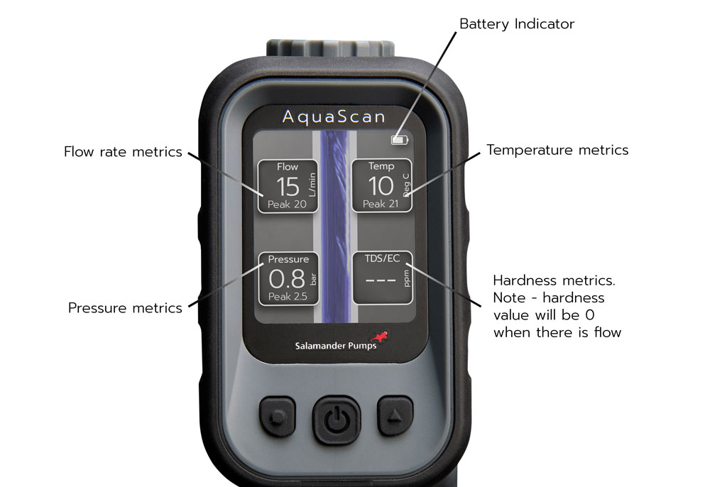
AquaScan is 4-in-1 digital water multimeter, combing the technology to measure pressure, flow, temperature, and hardness to provide precise water insight.
Adequate water pressure is essential for the proper functioning of appliances and fixtures within the property. Low water pressure can affect showers, washing machines or dishwashers. AquaScan can confirm the incoming mains water pressure into a property and accurately indicate that pressure is poor.
Water hardness is a problem which can cause limescale build-up, blocking pipes and reducing the efficiency of water using appliances such boilers and kettles. Knowing the water hardness is important to understanding what preventive measures can be taken to protect appliances, like installing a Salamander Pumps’ water conditioners.
AquaScan can easily measure the temperature of water, which is important not only from a performance perspective, but a safety one too. For example, it helps installers to determine if they need to install a Thermostatic Mixing Valve in a hot water system or to ensure that already installed TMV is operating correctly.
AquaScan incorporates four measurement tools therefore it allows you to take multiple types of readings at the same time, from one device. For example, on a combination boiler, if the temperature of water coming from the tap is not hot enough, it could indicate that the thermostat has failed, or that limescale has had a detrimental effect on flow and temperature reducing the efficiency of the boiler. All these issues would be highlighted by using AquaScan.
The AquaScan battery takes approximately 5 hours to fully charge with about 12 hours battery life.
When not in use, the unit will automatically shutdown after 10 min to preserve the battery charge.
AquaScan unit is supplied in a robust case with included connection accessories to allow the product to connect to multiple outlets, specification notepad, integral rechargeable battery, charged via USB C cable.
Note: the pressure should always read “0.0” before removing the unit from the outlet.
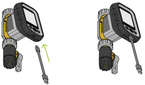
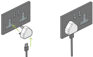
AquaScan has an integrated rechargeable battery and is supplied with a USB-C to USB charging cable.
Note: the pressure should always read “0.0” before removing the unit from the outlet.
Yes, you can use AquaScan to test a hot water temperature up to 85°C.
Note: It is advised to allow water to flow through the unit for 30-60 seconds for a more accurate reading.
AquaScan can be used to measure pressure, flow, temperature, and hardness (TDS/EC) whenever there is a need to record accurate measurements.
Static water – won’t show if there is a flow of water. Water hardness should be tested before a water softener to measure TDS/EC (total dissolved solids/electrical conductivity).
A garden tap is the best location to measure the incoming flow rate. When this isn’t possible, such as in properties where there is no outside tap, measuring the flow rate while multiple outlets are open is the best way to calculate the incoming flow rate. As this ensures any restrictive outlets do not impact the measurement.
The AquaScan is a portable, handheld unit which can be used at an outlet and requires no permanent install into a system to obtain readings of water flow, pressure, temperature, and hardness.
AquaScan provides live readings. It also shows ‘peak’ readings when taking a measurement to accommodate any fluctuations when testing.
AquaScan is suitable only to test clean water flow, pressure, temperature and hardness. The device shouldn’t be use for testing any other liquids (dirty water, oil, etc.)
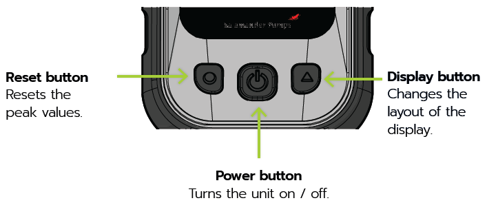
Press power button to turn AquaScan on and off.
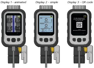
Live readings are shown on the digital display including maximum and live measurements of water flow, pressure, temperature, and hardness. While AquaScan turned on and connected to an outlet press reset button to reset peak values.
The user can easily select between alternative displays using the display button.
AquaScan is powered by a battery, rechargeable via a USB-C input.
Yes. However, current measurement methods can be cumbersome, have a high margin of error, and are often time-consuming. AquaScan accurately measure’s water flow, pressure, temperature, and hardness, giving instant digital readings.
AquaScan combines the technology to measure pressure, flow, temperature, and hardness in one unit.
AquaScan is designed for the following tasks/areas:
AquaScan has three control buttons:
When operated in accordance with the user guide, AquaScan does not require any particular maintenance.
Start by holding down the power button for 2 seconds. Make sure you press it firmly, a faint click should be heard.
What if AquaScan is still not powering on? Ensure that AquaScan is fully charged. Plug it in using the provided USB cable and let it charge for at least 7 hours.
If the unit still doesn’t turn on, double-check that you’re pressing and holding the power button for the full 2 seconds. If it doesn’t respond, try cleaning the control buttons with a damp cloth.
After cleaning, press and hold the power button again until the back-light activates and the display screen becomes visible.
Check both ends of the USB charging cable for any visible damage – replace if necessary.
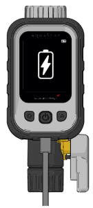
Fully insert USB-C charger into the charging port and into a power supply. With the power on, the battery level indicator in the top right of the AquaScan display will animate to indicate charging:
AquaScan power off and charging:
If AquaScan does not charge when using the original USB charger, use alternative power source to retry charging the unit.
If AquaScan feels hot or warm allow it to cool, moving it into a cooler area if it has been in the heat to lower the temperature, before recharging the unit. Never leave AquaScan in direct sunlight.
If you cannot plug in a charger, check charging port on handset for any blockage/debris.
While testing static pressure ensure the isolation valve on AquaScan is fully closed and no other outlets in the property are open.
If the pressure in the property is generally low, it may be too low to register during a dynamic pressure test.
The readings may vary during the day with fluctuations in the system. Taking readings at both ‘peak’ and ‘off- peak’ times will give a more accurate reading.
Expected measurement ranges and tolerances of AquaScan readings are:
Measurement | Measuring range | Accuracy |
Pressure | 0 – 10 Bar | 1.5% full scale |
Flow | 0 – 30 L/min | 5% of reading |
Temperature | 0 – 85 °C | 1.25% full scale |
Total Dissolved Solids (TDS) (hardness indicator) | 0 – 1000 PPM | 10% of reading |
The ’peak’ reading against the ‘live’ reading will help you see the increase/decrease in the measurement during testing.
Check that there are no leaks on the connection between AquaScan and the outlet/system/pipework for accurate measurement.
Ensure all outlets are closed and that there are no leaks in the pipework before the testing point. If the static pressure falls and the isolation valve on AquaScan is closed it may indicate a drop in pressure from the pipework or an outlet before the unit. The peak measurement will show the initial reading.
Check that there are no leaks on the connection between AquaScan and the outlet/system/pipework. Pressure will naturally fluctuate, particularly in mains-fed systems.
Heat exposure or extreme changes in temperature in the environment that AquaScan is being used in may affect the readings taken during the test. Allow water to flow through the unit for a minimum of 30 seconds to allow water and unit temperature to stabilise.
Open and close the isolation valve a few times to ensure that no air is trapped in AquaScan. Ensure the isolation valve is closed then wait 30 – 60 seconds before taking the reading.
Rinse any filtered water through the unit and retake measurement.
AquaScan has an automatic shut-off feature that activates after 20 minutes to conserve battery life. Simply press and hold the power button for 2 seconds to turn it back on and continue your measurements.
If AquaScan turns off again unexpectedly, check to ensure that the power button hasn’t been accidentally pressed during testing and that it isn’t stuck.
If the battery is low, AquaScan may turn off. Recharge the AquaScan for 7 hours and monitor the battery level indicator to ensure it’s charging properly before trying again.
If AquaScan feels hot during use, allow it to cool down completely. Avoid direct sunlight and store it in the provided carry case to protect it from overheating.
The AquaScan warranty may be invalidated in cases of product misuse, tampering, alterations, accidental damage and non-conformity with the instruction manual.
Before first use AquaScan must be fully charged!
To charge AquaScan follow the steps below:
1. Always use the USB-C to USB cable supplied with AquaScan.
2. Plug the USB-C into USB-C port on AquaScan.
3. Plug USB into a compatible 5V power supply.
4. When AquaScan is turned on, the battery level indicator will change to ‘charging’:
Battery level indicator will animate to indicate charging:
When AquaScan is turned off and charging the display below will be shown.
AquaScan measures the total dissolved solids (TDS) in the water in parts per million (PPM) to provide an indication of water hardness.
The higher the reading the more likely limescale will build up on pipes and appliances in the home. Limescale build-up restricts flow and increases the amount of energy required to heat water in appliances such as kettles, boilers, washing machines and dishwashers.
Source: Drinking Water Inspectorate “Hardness of Water”
Hard water (high limescale content) can be treated with products such as Salamander Pumps’ range of water conditioners.
In general applications where the flow rate is known to be low or there is relatively heavy scale build-up inside the pipe already, a conditioner one size smaller than the pipe diameter is recommended. Therefore, it is important for the installer to check the flow rate entering the property.
An increase in temperature
An increase in water temperature can cause calcium and bicarbonate to come out of solution and deposit as scale (calcium carbonate) on the nearest receptive surface. This effect can be seen in heat exchangers, heating coils taps & shower heads.
An increase in pH (“potential of hydrogen”)
Pressure reduction that occurs as water is released from the system to atmospheric pressure allows carbonic acid to be released in the form of CO2. The reduction of this acidic component in solution causes an increase in pH and the potential for scale to form.
Salamander Pumps’ catalytic water conditioners treat hard water and prevent scale build-up.
Salamander Pumps’ catalytic water conditioners treat hard water and prevent scale build up. They use an alloy core to create turbulence and a catalytic reaction, which changes the calcium carbonate, found in the water, from calcite to aragonite. There are no chemicals or salt used in this process, the calcium carbonate is still present but can pass through the system without depositing as scale. Nothing is added or removed from the water, so the water is safe to drink.
The treated water also has a greater capacity for absorbing scale, so pre-existing deposits are gradually broken down and absorbed.
Water conditioners are an effective solution for hard water problems.
They work by altering the physical structure of the calcium carbonate in the water. This process does not remove any minerals, but rather prevents them from adhering to surfaces and forming a hard scale.
The benefits are not just limited to the prevention of limescale, but the Salamander Pumps water conditioners also improve the efficiency of appliances and heating systems, reducing energy costs, and prolonging the life of appliances.
Salamander Pumps’ water conditioners have a warranty of 10 years.
Catalytic water conditioners do effectively prevent the build-up of calcium that causes limescale in your pipelines, heating systems, and large and small appliances.
Yes, you can drink conditioned water because nothing has been added or taken away from the water.
Learn more about Salamander Pumps water conditioners by the link.
It is crucial to choose the right water conditioner to get results. Selecting the wrong size conditioner including using a larger diameter than needed can compromise water delivery and affect treatment quality.
Water conditioners size is selected based on the amount of water flowing through them. Check the flow rate of the incoming water and match this to the relevant water conditioner:
In general applications where the flow rate is known to be low or there is relatively heavy scale build-up inside the pipe already, a conditioner one size smaller than the pipe diameter is recommended. Therefore, it is important for the installer to check the flow rate entering the property.
Catalytic water conditioners, also known as salt-free water softeners, do not use ion exchange to remove the hardness minerals like their salt-based counterparts.
Salamander Pumps water conditioners utilise a non-sacrificial lead-free alloy core with a special surface. As water passes over the core a catalytic reaction takes place. The minerals’ form is changed to a hardness crystal that does not adhere to surfaces.
For the ½” & ¾” whole house water conditioners we recommend that they are fitted after the stop tap entering the property, this will ensure that the whole property will have conditioned water.
The ½” single point water conditioner can be fitted either to the mixer valve outlet or directly before the shower head.
If the water conditioner is being fitted on an open vented (Gravity) system, it can be fitted further downstream to the cold-water tank where the water is held usually in a loft space. This will ensure that the water supplying the hot water cylinder has conditioned water.
If being used on an in-coming mains fed system, it should be fitted before any appliances like combi boilers or unvented cylinders and ideally before any Salamander Pumps’ product like an AccuBoost or TankBoost. In some cases, it might have to be fitted after the kitchen cold water drinking tap.
Learn more from the article “Water Conditioner vs Water Softener. Which One to Choose?“
Both the ½” & ¾” water conditioners have flow direction arrows engraved on the outside diameter.
The ½” single point water conditioner can be fitted in any orientation as it has a parallel alloy core.
All Salamander Pumps’ water conditioners can be installed both vertically and/or horizontally.
Water that passes through a Salamander Pumps’ water conditioner will remain conditioned for up to 3 month if it is stored in a tank.
No, the water conditioner should be installed before the pump and if correctly installed conditioners will have a negligible impact on pressure drop – to a maximum of 2%.
As part of WEEE Directive, you just need to dispose your water conditioner in an appropriate waste collection point/ recycling centre.
No, the correct size of water conditioner is selected based on the water flowing into the property and is not limited by the number of outlets in the house. Check the flow rate of the incoming water and match this to the relevant whole house water conditioner:
Single Point Water Conditioner can be used only on a single outlet.
No, a water conditioners installation doesn’t affect the warranty of the pump. But we still recommend installing water conditioner to prevent the pump from the limescale to help extend the life expectancy of the product.
Water hardness is caused by dissolved calcium and magnesium. The hardness of water supply in the UK will very depending on location. The hardness of water, expressed in mg/L CaCO3 (calcium carbonate), can be classified as shown below:
Water Hardness (mg/L CaCO3) | |
Soft | up to 100 |
Slightly hard | 100 -150 |
Moderately hard | 150 – 200 |
Hard | 200 – 300 |
Very hard | More than 300 |
Water described as “hard” contains high amounts of dissolved calcium and magnesium. Hard water is not a health risk but is a nuisance because it can damage your home’s plumbing and heating systems.
Scale acts as an insulator, as it builds up it takes more energy to heat or cool water, making appliances less efficient and increasing energy consumption. For every 0.005’’ of scale energy demand will increase by 5%.
Both shower pumps used in gravity fed systems and mains boosting solutions can be negatively impacted on by hard water and lime scale deposit build up, resulting in noisy operation and often leading to premature product failure.
Water conditioners are an effective solution for hard water problems. They work by altering the structure of calcium carbonate in the water, preventing them from forming scale. This process does not remove any minerals but rather prevents them from bonding to surfaces and forming a hard scale. The benefits are not just limited to the prevention of limescale but will also lower energy costs and extend appliance life.
Customer Support
Find an Installer
Visit our installer map to search for an installer in your local area.
Find an installer
Warranty Registration
Provide your installation details in our quick and easy form to register your product's warranty.
Register your warranty
Salamander Pumps Shop
Visit Salamander Pumps' official online store and order boosting products and accessories for your next installation.
Shop now